Installation
The installation of the Single Quantum Eos system is typically performed on-site by a Single Quantum service engineer, an authorized representative, or the customer with remote guidance. However, this section provides a summary of the installation process to enable users to relocate the system or rearrange/replace components if needed. The installation instructions are presented as a series of clear, concise steps, each highlighting important considerations to keep in mind.
Installation instructions
Check the Shipment Upon Delivery If the system was shipped to a new location or upon the initial delivery, shock and tilt watches should always be inspected. Any activated watches should be reported to the delivery service before accepting the items.
Verify Components Ensure all necessary components are present. The full list of components is discussed in Main components
Electrical Supply Confirm the electrical supply on installation site meets the required circuit ampacity (16 A). Check that the electrical supply has suitable configuration (mains voltage and frequency) and socket types.
Compressor Placement and Connection of Helium Flex Lines Position the compressor in its final location, ensuring the helium lines can easily reach the designated spot for the cryostat, and that compressor is within the reach of cooling water lines (for water-cooled model) or has enough space for air circulation (for air-cooled model). See the OEM manual for cooling requirements. Connect cold head power cable and helium flex lines to the compressor following the guidelines from Guidelines for connecting and disconnecting helium flex lines.
Assemble the Vacuum Pump Assemble the included components of the vacuum pump in the following order: pump, T-piece, pressure sensor, reducer, vacuum hose. The KF40 o-ring with metal mesh should be placed directly on the turbo pump. If there was no pump ordered with the system, arrange a suitable oil-free vacuum pump. It must be able to reach <1E-5 mbar pressure and compatible with the KF16 connection port on the cryostat.
CAUTION Always wear gloves when handling vacuum components to prevent contamination of surfaces and vacuum leaks.
Place the Cryostat Position the cryostat in its final location, ensuring access to vacuum, helium, and electrical connections.
Attach the Cold Head Cable and Helium Flex Lines to the Cryostat Follow the guidelines from Guidelines for connecting and disconnecting helium flex lines.
Set Up the Vacuum Pump Place the vacuum pump near the cryostat and connect it.
Test the Vacuum Pump (a) Leave the valve on the cryostat closed. Turn on the pump and confirm it reaches full speed and a pressure of at least 1E-5 mbar (typically within 10 minutes).
(b) If the required vacuum is not reached, turn off the pump, inspect connections, and retry.
(c) After the check, turn the pump off and wait for the turbo to fully stop.
Open Vacuum Valve After the pump has fully stopped, slowly open the vacuum valve on the cryostat and restart the pump. Wait until the cryostat is evacuated to at least 5E-5 mbar.
Place and Connect the Driver (a) Position the driver appropriately. (b) Connect the SMA cables between the driver and cryostat using an SMA torque wrench (check the characterization sheet of the system for any information on connection scheme between driver and cryostat channels).
(c) Connect the Fischer cable between the driver and the cryostat. Align the red dot on the connectors and push it until it clicks.
(d) Connect the driver to its power supply. (e) Connect the driver to network or directly to a computer via LAN cable. 12. Driver Software Access for Atlas driver: Turn on the driver using the LED button. Wait until the color of power button becomes blue and access the software on the computer via web browser. Use the default IP address 192.168.1.1, username user, and password websq. for Retina driver: If the driver was connected to a local area network, it is required to find the ip address assigned to the driver in this network using its MAC address.
Temperature Check Navigate to the temperature tab and ensure the readout corresponds to room temperature (~300 K). Once the system is fully assembled, it needs to be evacuated the to minimum recommended pressure and then cooled down. Once system is cold, the user may check its performance with a series of quick checks listed in Basic system performance check.
Guidelines for connecting and disconnecting helium flex lines
Closed-cycle refrigeration systems are designed to operate without any noticeable loss of helium gas (coolant). However, mistakes, especially during the connection or disconnection of helium flex lines, can lead to helium leakage. This set of instructions is intended to prevent helium loss by outlining the correct procedures for connecting and disconnecting helium flex lines. By following these guidelines, users can avoid common errors, ensuring that no helium is lost from the system.
When arranging the helium flex lines, ensure a bending radius of at least >=150 mm for intermediate sections and >=180 mm for terminal sections. Bending the flex lines beyond these limits may cause permanent damage and helium leakage, so it must be strictly avoided.
Ensure that the connection ports on the helium compressor, helium flex lines, and cold head are free of any debris. Use compressed air or gently wipe off any debris with your finger while wearing gloves. The helium ports on the compressor and cold head must have an o-ring to properly seal the connection. The o-rings should sit on the perimeter of the port, as shown in Figures a and c. Ensure that the o-rings are neither damaged nor missing. The ports on the helium flex lines should not have o-rings on the perimeter.
Record the helium charge pressure on the compressors front panel. If the charge pressure is below 1.8 MPa for the CNA-11 compressor model or below 200 psi for the F-20L model, do not proceed further without contacting Single Quantum Service (see Contact contact details). Typical charge pressure values are 1.95 - 2.0 MPa and 210 - 230 psi for the CNA-11 and F-20L compressor models, respectively.
Always connect the helium flex lines to the compressor first, then to the cold head. Once the helium flex lines are connected, move the compressor and cryostat as little as possible to prevent sudden loosening of couplings followed by helium loss.
(a) Start by connecting the helium Return flex line first, followed by the helium Supply line.
(b) Guide each line to its designated port, ensuring it remains straight (Figure d). The line should not be under tension.
(c) When attaching or detaching the lines, use two wrenches: one to hold the coupling on the cold head/compressor and another to tighten the nut on the flex line. Do not apply excessive force when securing the connections.
Record the final helium charge pressure on the compressors front panel. If the charge pressure is below 1.8 MPa for the CNA-11 model or below 200 psi for the F-20L model, do not proceed further without contacting the service team.
Attach power cable between compressor and cold head. Helium flex lines should only be disconnected when the system is powered off and at room temperature. To disconnect the helium flex lines, follow these instructions in reverse order; disconnect helium Supply line first, then the helium Return line. Use dust caps on all helium ports when storing the flex lines and other system components.
WARNING Never disconnect helium flex lines until system has reached room temperature.
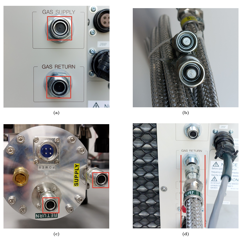
Connection of aeroquip couplings.